1. Main Technical Parameters and Economic Indicators
This high-temperature tunnel kiln adopts an open-flame intermittent combustion method with intermittent car feeding, specifically designed for firing corundum-mullite refractory bricks. The kiln is 50 meters long and 5 meters wide internally, with heights of 95 meters from the kiln car platform to the kiln roof and 75 meters respectively. It can accommodate 25 kiln cars, each carrying two stacks of bricks. The firing temperature reaches 1650℃, and the entire firing cycle takes 46 hours. The kiln uses natural gas as fuel, with an energy consumption of approximately 1500 kcal per ton of bricks. Both kiln temperature and pressure are automatically controlled, with temperature control accuracy within ±2℃.
2. Main Structure and Working System of the Kiln
The high-temperature tunnel kiln has a complex structure, encompassing the kiln body, the kiln head enclosed air curtain and exhaust system, the stirring air system, and the combustion system. It also includes a kiln tail cooling system, an undercarriage cooling air system, a waste heat utilization system, kiln cars, and an automatic control system. The kiln incorporates new technologies in its structure, high-temperature hot air combustion technology, waste heat utilization, and automatic control system, resulting in significantly superior high-temperature firing control precision and energy-saving performance compared to traditional high-temperature kilns.
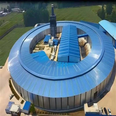
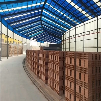
1. Kiln Main Structure The kiln's steel structure is based on reinforced steel columns, with the outer surface treated with high-quality steel plate paint for enhanced aesthetics. The kiln, 50 meters long, is carefully divided into three zones: a preheating zone, a firing zone, and a cooling zone. The firing zone is lined with corundum mullite bricks, followed by high-temperature lightweight insulating bricks, insulating fillers, and asbestos-free hard calcium silicate boards, ensuring the kiln's refractoriness and insulation. The kiln roof features an arched design, which not only helps reduce high-temperature expansion but also ensures that its lining uses the same refractory bricks as the firing zone, thus maintaining the overall stability of the kiln. At the preheating zone's arch, the designers cleverly constructed three staggered baffles, allowing the hot airflow above the arch's base to flow downwards. This optimized the temperature distribution in the preheating zone without negatively impacting the exhaust draft. Furthermore, to address the significant lateral thrust of the arch, the designers employed a combination of high-quality flat bricks and lightweight insulating bricks on the outer side of the arch's base bricks, effectively improving the insulation performance in this area.
High-temperature kilns place high demands on burner bricks. Because integral burner bricks are prone to cracking under large temperature differences between the hot and cold ends, and have a short service life and are difficult to replace, the burner bricks in this kiln were carefully designed as four separate pieces assembled together, significantly extending their service life. In addition, after long-term operation, the inner walls on both sides of the firing zone of traditional high-temperature tunnel kilns tend to bulge inwards due to high-temperature expansion. To solve this problem, the refractory bricks lining the kiln walls of this kiln were designed with an interlocking structure. Practice has proven that this design significantly reduces the inward bulging of the kiln walls.
2. Kiln Head Enclosed Air Curtain and Exhaust System
To maintain stable kiln pressure and prevent firing temperature fluctuations, the kiln head and tail are not equipped with kiln doors, but instead sealed with air curtain hoods. The air curtain hoods are located on both sides of the kiln head and the kiln roof, forming a closed air curtain through exhaust ventilation, thus ensuring clean product entry for firing. The exhaust system combines multi-point exhaust within the kiln with centralized exhaust by external fans. Multiple pairs of exhaust ports are located on both sides of the preheating zone, and the temperature profile of the preheating zone can be precisely controlled by adjusting the opening of the exhaust ports. Additionally, each exhaust port has a cold air dilution port on its outer side to draw in outside air when necessary to reduce the exhaust temperature.
3. Stirring Air System
Addressing the temperature difference problem caused by gas stratification in the preheating zone of traditional tunnel kilns, this design not only adopts kiln roof slab flow separation and multi-point exhaust measures within the kiln, but also adds a stirring air system to the upper part of both sides of the preheating zone. The system draws in cool ambient air via a fan, which then flows through a main pipe, branch pipes, and ball valves into the upper channel of the kiln. This effectively agitates the airflow, prevents air stratification, and reduces the temperature difference between the upper and lower parts of the preheating zone. Its compact and staggered air inlets ensure effective agitation while reducing energy consumption.
4. Combustion System
To meet the high-temperature, constant-time requirements of the fired products, the firing zone occupies a significant proportion of the kiln's total length, with a corresponding number of burners. By flexibly adjusting the number and location of the ignited burners, the position of the high-temperature point in the firing zone and the high-temperature constant-time can be easily adjusted, thus adapting to the firing process requirements of different product formulations and demonstrating greater adaptability and flexibility in the firing process.
The burners are staggered on both sides of the kiln, directly facing the combustion channel between the brick stacks on the kiln cars. This ensures that the high-speed combustion airflow forms a certain circulation within the kiln, rather than relative flow and mutual interference. This design results in a uniform temperature within the kiln, avoiding the temperature fluctuation problems that may occur in traditional tunnel kilns. Furthermore, this kiln employs direct combustion between the products inside the kiln, eliminating the need for combustion chambers on the kiln side walls, simplifying the side wall structure, and effectively providing heat insulation.
It is worth noting that the combustion method of this kiln differs significantly from that of traditional tunnel kilns. In traditional high-temperature tunnel kilns, the inner cavity of the burner bricks is often large, and the combustion air mainly enters the kiln through the burners or combustion chambers. However, in this design, the burner bricks are shorter and have smaller inner cavities, with only a small amount of cold air entering the kiln through the burners, primarily for cooling the burners and assisting in air blowing. The majority of the combustion air comes from the cooling air blown in by the cooling zone. This design not only significantly improves energy efficiency but also makes high-temperature heating and high-temperature constant-temperature operation easier.
In addition, the kiln is equipped with a kiln tail cooling system, an undercarriage cooling air system, and a waste heat utilization system, further optimizing the kiln's performance. Through the synergistic effect of these systems, the kiln can efficiently cool the products, prevent excessively high temperatures under the carriages, and fully utilize waste heat, achieving efficient energy utilization.
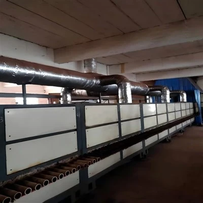
The waste heat utilization system in this design comprises four key components: first, a cooling zone responsible for cooling the hot air; second, an under-car cooling system to reduce the kiln car temperature; third, cooling air radiating from the outer surfaces of the kiln walls and roof to aid in heat dissipation; and finally, flue gas heat exchange air to fully utilize the waste heat in the flue gas. Because the outer surface temperature of the high-temperature kiln is higher than that of traditional tunnel kilns, we specifically added corrugated plates supported by steel sections to the kiln roof in the high-temperature zone, forming a heat exchange space with the outer arched roof. Simultaneously, the outer layer of the kiln wall is designed as a hollow wall, allowing cold air to enter through a row of small holes near the ground, mix with the heat exchange air from the kiln roof, and then be extracted centrally. Furthermore, a metal heat exchanger is installed on the main exhaust duct outside the kiln to further utilize the waste heat of the flue gas. All four components of waste heat air are sent to the drying kiln, fully meeting the drying requirements of the products.
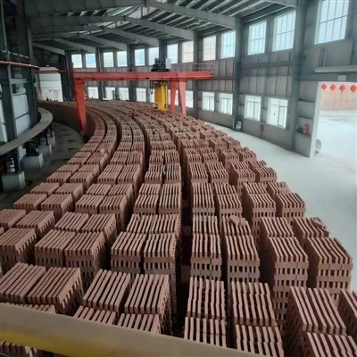
The kiln cars are constructed of steel sections and equipped with high-temperature bearings, capable of withstanding temperatures up to 300℃. Regarding the kiln body materials, the kiln platform is constructed using sintered mullite bricks with excellent thermal shock resistance. The dry-laying method significantly reduces the frequency of kiln car maintenance and extends its service life.
The kiln's automatic control system encompasses temperature and pressure control, as well as safety alarm functions. Firing temperature is precisely controlled by a computer, including a computer, AI-powered controller, solenoid valves, electric actuators, and thermocouples. The system is also equipped with data acquisition cards and internal/external isolation devices, programmed using dedicated industrial control software. Kiln pressure control is achieved through frequency conversion technology, adjusting the exhaust fans, cooling fans, and hot air extraction fans, offering high precision and energy efficiency. Furthermore, the system provides a manual operation mode for process exploration and handling emergencies.
This kiln uses natural gas as fuel, making gas supply safety paramount. Therefore, a main solenoid valve is installed on the main gas supply pipeline, and section solenoid valves are installed on each ring pipe. In the event of a power outage, these solenoid valves will immediately and automatically cut off the gas supply, effectively preventing natural gas from entering the kiln. In addition, we have equipped it with an alarm system to issue an alarm when the blower system malfunctions and simultaneously activate the solenoid valve to cut off the gas supply, ensuring the safety of the kiln operation in all aspects.